The result is a slightly FMed pulse train that averages 32,768 Hz over a one-second interval.
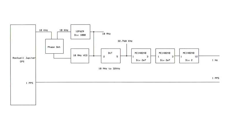
The test set shown here was used to verify the code:
The DUT was driven with 10 MHz and the output divided by 2e15.
The 1PPS line was used to trigger a delayed-sweep oscilloscope and an edge
of the 1 Hz line was observed to be stable on the delayed 50 uSec/cm sweep.
Adding 1 NOP instruction per second to the code caused the 1 Hz edge to drift
by the calculated 24 uSec per minute, thus testing the test-set.
The Microchip PIC code below fits easily into the 8-pin 12F629.
;****************************************************************
;                                                               *
;    Filename:	     10M32K.asm                                 *
;    Date:           09/20/2008                                 *
;    File Version:   0.01                                       *
;                                                               *
;    Author:         Peter Putnam                               *
;    email:          peter@ni6e.com                             *
;                                                               *
;    Tip o' the Tam:  /tvb                                      *
;                                                               *
;****************************************************************

; Generates 32768 Hz from 10.000  MHz
;  Loop 9632 times with 39 counts per loop in Part 1
;  Loop (65536-9632)= 55904 times with 38 counts per loop in Part 2
;   Toggle the output pin at end of each minor loop.
;   The first 9632 times through the loop are longer by 400 nS.
;    Repeat to infinity and beyond
;
;
; 10 MHz input at CLKIN, pin 2
; 32768 Hz out at GPIO2, pin 5
;   100 nSec per clock cycle
; 	400 nSec per instruction cycle
;
; /MCLR tied hi internally

;****************************************************************
;                         12F629                                *
;                       +---------+                             *
;                     1 |         | 8                           *
;            5.0 V  ----+         +----  GND                    *
;                     2 |         | 7                           *
; 10.0 MHz In CLKIN ----+         +----  GP0                    *
;                     3 |         | 6                           *
;              GP4  ----+         +----  GP1                    *
;                     4 |         | 5                           *
;              GP3  ----+         +----  GP2  32768 Hz Out      *
;                       |         |                             *
;                       +---------+                             *
;                                                               *
;****************************************************************

	list	  p=12F629
	#include  p12F629.inc
	radix     hex


  __config _EC_OSC & _MCLRE_OFF & _WDT_OFF


;=======================================
;Bit RP0 is bank select bit
;
;       0: Bank 0
;       1: Bank 1
;
;=======================================
w               equ       0     ; to w register
f               equ       1     ; to file register or memory address
;=======================================
;register definitions
                cblock    0x20
                DST
                DST1
                VAR
                VAR1
                d1
                x1
                endc
;=======================================

Reset:
                org      0x00

Init:
                                                        ; Initialize Ports
                bcf STATUS,RP0                          ; Bank 0
                clrf GPIO                               ; Init GPIO
                movlw 0x07                              ; Set GP<2:0> to digital IO
                movwf CMCON
                bsf STATUS,RP0                          ; Bank 1
                movlw b'00110000'                       ; Set GPIO<5:4> as inputs, (GPIO4 in only)
                movwf TRISIO                            ;  and GPIO<3,2,1,0> as outputs
                bcf STATUS,RP0                          ; Bank 0


                movlw   0x5F                            ; Counter setup for first pass, Part 1 loop
                movwf   DST
                movlw   0xDA
                movwf   DST+1

;               movlw   0x9F                            ; Counter setup for Part 2 loop
;               movwf   VAR
;               movlw   0x25
;               movwf   VAR+1


; ******************************** Part 1 Loop *******************************

part1:                                                  ; Part 1 counter set to repeat 9632 times
                                                        ;  Inner loop = 39 instruction cycles
                movlw   0x07                            ;  22 cycles
                movwf   d1
delay_22a
                decfsz  d1, f
                goto    delay_22a
                goto    $+1                             ; 2 cycles

                movlw   0x9F                            ; Counter setup for Part 2
                movwf   VAR                             ;  repeated many times here in Part 1
                movlw   0x25                            ;  keeping it inside a counted loop
                movwf   VAR+1


                movlw   b'00000100'                     ; Toggle output pin
                xorwf   GPIO, f                         ; Back to this point in Part 1 loop
                                                        ;  must be 39 instruction cycles

                                                        ; Increment 16 bit counter, set Z when full
                                                        ;  count 9632 passes, then set Z flag
                incfsz  (DST),W                         ; Add one to low byte
                decf    (DST)+1,F                       ; No carry (negates next step)
                incf    (DST)+1,F                       ; Add one to high byte
                movwf   (DST)                           ; Store updated low byte back
                iorwf   (DST)+1,W                       ; Set Z flag

                btfsc   STATUS, 2
                goto    part2a
                goto    part1
part2a:
                nop                                     ; required because bit test is single cycle
                                                        ;  when program counter is not modified
                                                        ;  otherwise, it is 2 cycles

; ******************************** Part 2 Loop **************************

part2:                                                  ; Part 2 counter set to repeat 55904 times
                                                        ;  Inner loop = 38 instruction cycles
                movlw   0x07                            ; 22 cycles
                movwf   x1
delay_22b
                decfsz  x1, f
                goto    delay_22b
                nop                                     ; 1 cycle

                movlw   0x5F                            ; Counter setup for Part 1
                movwf   DST                             ;  repeated many times in Part 2 loop
                movlw   0xDA                            ;  keeping it inside a counted loop
                movwf   DST+1

                movlw   b'00000100'                     ; Toggle output pin
                xorwf   GPIO, f                         ; Back to this point in Part 2 loop
                                                        ;  must be 38 instruction cycles

                                                        ; Increment 16 bit counter, set Z when full
                                                        ;  count 55904 passes, then set Z flag
                incfsz  (VAR),W                         ; Add one to low byte
                decf    (VAR)+1,F                       ; No carry (negates next step)
                incf    (VAR)+1,F                       ; Add one to high byte
                movwf   (VAR)                           ; Store updated low byte back
                iorwf   (VAR)+1,W                       ; Set Z flag

                btfsc   STATUS, 2
                goto    part1
                goto    part2

                end